
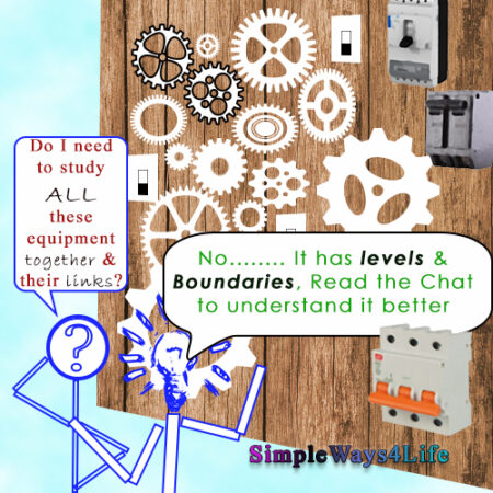
In the this chat we shall demonstrate failure modes of some sample equipment and some guides to properly level your system analysis. As we had defined Failure Modes in our previous chat; A failure Mode for a Function Failure is one of the ways that this Failure could happen. In other words , it is one of the causes of the Failure. To know the possible causes of failures, there is the preliminary step of selecting the right size of the system that you will analyze. We need to keep in mind that our target is to evaluate our maintenance tasks, its cycle, select who will do them and add any missing tasks or measures needed to maintain the functions running.
Selecting the right size of the system and delving to the right depth
You will find most of the examples publicly discussed speaking about equipment that are popular across many industries as pumps and compressors. Specific systems as electrical distribution systems and transforms are rarely studied. Also the specific systems of special industries as Steel making are studied only from those working in that field. You will find few published examples of them.
The target from using typical examples is to generate a model that can be easily understood in all sectors.
You can start with a pump as a standalone equipment. However, a pump with its driving motor, power supply, sensors and valves is better due to interconnected failures. Further more, for skid mounted pumps when one of them is standby, this would generate a more realistic study. The suction tank and the delivery circuit can be studied separately if they include more equipment that would include failures not related to the pump skid.
However in this chat we shall take a different approach by studying an electrical distribution panel. It exists in any working place regardless of its size. Nevertheless, this model is seldom used as an example to demonstrate failure modes. I hope it will inspire you.
Example of the Failure Modes recording
Electrical System
Consider an Electrical distribution panel that supplies the electrical power to your pump house or a set of conveyors. That’s different from MCC panel that provides the switching ON and OFF based on the PLC or other logic controls from the operating context. The first point we need to consider is setting the boundaries of the system under study. There is no right or wrong selection for the boundaries. However, we need to make sure that the all the equipment are either included in this subset or the following one or the previous one. So, there are no overlooked equipment that we hadn’t considered it. Considering an equipment in our study doesn’t mean that we need to set some maintenance activities for it. On the contrary, we might end up mindfully labelling it “No scheduled Maintenance”.
System Boundaries
Assume that we shall set the input boundary of the panel at the incoming circuit breaker. So, we shall include the main circuit breaker in our study and its terminals but the supplying cables will be part of the upstream whether a transformer or a bigger distribution panel. The next boundary is the outgoing one. Here, we shall include the cables going to the loads in our study of this electric panel. Another point to consider, is the control power generated within the panel or supplied from another source? Consequently this might be a third boundary for our electrical panel.
System parts
It is wise to divide the system into parts. This will help in identifying the failures of the individual parts that affect the system or subsystem functions. Also, it will facilitate digging deeper into a reasonable root cause. Here, there is a due clarification. “A reasonable root cause” implies that there is an action within our reach that can be taken. However, this differs from one work place to the other.
The parts of the electric panel subsystem we had chosen for the failure modes analysis are: The panel body, the main circuit breaker, the distribution outgoing breakers, the internal distribution cables or busbars, and the outgoing cables.
Examples of business environment affecting the level of analysis i.e. level of system parts.
I would like to point out two working environment I had personally experienced. In a remote work location where I was a part of a team running a manufacturing site, the owner pays our company a constant rate in proportion to the produced units. This includes the man hours and the operation and maintenance fees. This is not far from the private utilities supply of electricity, water or fuel. There also the consumer pays a constant predetermined fee. As a company owning or running this utility you need to ensure that this fee covers all your cost and profit.
There, in company one, when a circuit breaker fails, we dismantle and repair it. We replace its internal parts, calibrate it , test it and put it back as a usable spare. Anyhow we were the ones who will be using it back so we were doing our best to save us future troubles. In this model the circuit breaker internal parts and their failure were individually considered as part of the subsystem.
In another work location for one of the heavy industries, the uptime was the sole KPI -in good times of course-. When selling prices goes down, the cost was part of the equation. However in both situations, we used new spares and applied strict calendar based preventive maintenance. Parts changed for its prescribed life span were kept for emergency. And alternative resources for spare parts were considered to reduce cost. As a conclusion for this second example, whole circuit breakers were our analysis limit.
System\Subsystem Functions
Next step, we need to know the functions that this electrical panel provides. There is a main function, and some other secondary functions. The main function can be: providing electrical power to the pumps skid or the set of conveyors. Secondary functions can include:
- Safely enclosing the electrical power distribution breaker
- Providing safe access to maintenance technicians
- Providing clear feedback and labelling of the status of its internal circuit breakers
- Allow safe clear isolation of individual loads for maintenance
- Protect the mechanical loads supplied from gradual or sudden overloads.
- Auto switching OFF the loads in case of electrical current leakage
- Limiting the electrical power withdrawn from the upstream source
FF (Function Failures)
Each of the main functions and the secondary functions is expected to have at least ne Total Failure and one partial Failure.
| Function | Function Failure |
|---|---|
| 1.Providing electrical power | A. Totally Not providing electrical power to all loads. |
| B. Partially not providing electrical power i.e. to one or more of the loads | |
| 2.Safely enclosing the electrical power distribution breakers | A. Electrical panels internal parts are exposed |
| B. Rodents and rain can enter the panel | |
| 3.Providing clear feedback and labelling of the status of its internal circuit breaker | A. No external indications on the panel outer or inner doors |
| B. Indications or labels are worn out or not working | |
| 4.Allow safe clear isolation of individual loads for maintenance | A. Can not be used to isolate individual loads |
| B. It is difficult to apply lockout and tagout | |
| 5. Protect the mechanical loads supplied from gradual or sudden overloads. | A. There is no overload or motor stalled protection |
| B. Mechanical load is damaged before the trip of the circuit breaker | |
| 6. Auto switching OFF the loads in case of electrical current leakage | A. Operators feels electrical surges in the equipment body |
| 7. Limiting the electrical power withdrawn from the upstream source | A. The upper stream trips earlier than the main circuit breaker of the panel |
FM (Function Modes)
We had came up for the demo of the power distribution panel with one (1) main function and six (6) secondary functions. Followed by about twelve (12) function failures. Consequently in the following table it result in around forty eight (48) Failure Modes. Even though it looks more than enough for one electrical distribution panel; there are more failure modes to consider. And, those failures and failure modes vary from one working place to the other based on the business environment and operation context. Next chat shall bring more examples from various disciplines in the maintenance field.
| Function | Function Failure | Failure Mode |
|---|---|---|
| 1.Providing electrical power | A. Totally Not providing electrical power to all loads. | 1. Main Circuit Breaker tripped 2.Main circuit Breaker not switched ON 3. Upper stream circuit breaker tripped 4.Upper Stream circuit breaker not switched ON 5. Wrong coordination between panel main and load breakers |
| B. Partially not providing electrical power i.e. to one or more of the loads | 1.The related Circuit Breaker is tripped 2. The related circuit Breaker is switched OFF 3. Loosen cables to this load 4. Out going Cables cut or not connected | |
| 2.Safely enclosing the electrical power distribution breakers | A. Electrical panels internal parts are exposed | 1. Panel door is left open 2.Panel door is broken 3. Panel door lock is not working 4. No available key for the panel door |
| B. Rodents and rain can enter the panel | 2. Panel inlet is not sealed 3. Panel outlet is not sealed 4. Panel door not closed (refer to 2.A) 5. Panel rusted and worn out 6. Panel hit and damaged | |
| 3.Providing clear feedback and labelling of the status of its internal circuit breaker | A. No external indications on the panel outer or inner doors | 1. Wrong Design 1.1 No specification set |
| B. Indications or labels are worn out or not working | 1. Indication LED are burned 2.Wrong material used for labeling 3. Wrong design for the panel (no protection for indicators and labels) 4. No spare parts 4.1 Spare parts are not available, discontinued | |
| 4.Allow safe clear isolation of individual loads for maintenance | A. Can not be used to isolate individual loads | 1. Load cables bolted to internal busbars 2. No labels for the loads 3. One circuit breaker feed more than one load 4. Panel has a common Switch that need to be OFF to access the panel 4.1 wrong design |
| B. It is difficult to apply lockout and tagout | 1. Circuit breakers are not provided with lockout and tagout handles or tools 2. Lockout and tagout tools are not matching this panel 3. Wrong design of the panel 4.Wrong purchase of lockout and tagout | |
| 5. Protect the mechanical loads supplied from gradual or sudden overloads. | A. There is no overload or motor stalled protection | 1. Tripping coil is failed stuck 2. Tripping spring failed 3.Protection relays or plugins of the breakers are hidden failed 4.Circuit Breakers are not equipped with this protection |
| B. Mechanical load is damaged before the trip of the circuit breaker | 1. Protection is hidden failed 2.Wrong setting of the protection 3.Wrong sizing of the protection | |
| 6. Auto switching OFF the loads in case of electrical current leakage | A. Operators feels electrical surges in the equipment body | 1. Power supply panel is not provided with earth leakage protection 2.EarthLeakage wrong setting 3. Earth leakage protection hidden failed |
| 7. Limiting the electrical power withdrawn from the upstream source | A. The upper stream trips earlier than the main circuit breaker of the panel | 1. Panel main breaker failed 2. Panel main breaker wrong setting 3.Upstream breaker wrong setting |
If you feel you need help with any of these ideas we discussed, request a Management Consultancy or Coaching Services From our Store


One Comment